Last Month I’ve sourced DEDuino PCB. REV.D for the Main Board and the Indexers out to production (ITEAD studios) . Key Feature of the RevDs is the switch to I2C, and the switch to Shield type form-factor for Supporting Arduino Due. However, I’ve also incorporated Uno and Mega support while at it.
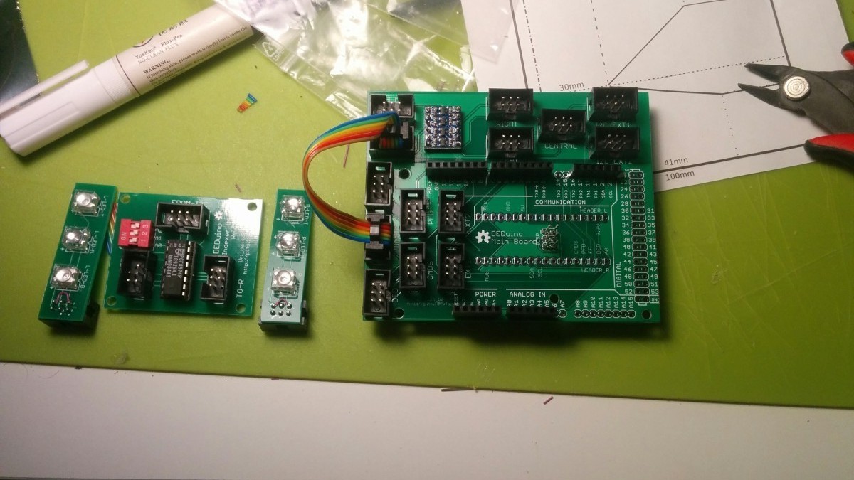
I’ve finally got the boards in the mail and started assembling them.
Read more for the rest of the process and features.
As the Project grew, and more and more displays and lights added, it became clear that the Arduino Micro would not be enough. So I started shifting efforts towards the Due which is much more potent in driving multiple screens (due to the large memory) and do more performance wise because of the extra oomph (84mhz compared to 16).
But the old board, was designed specifically for the Micro. So when going for the Due, I opted to go for the shield type boards, and with that, use it as a shield for Mega and Uno as well. (Arduino Mega is still not supported by the Project, but it can be made to work).
So after designing the thing, and shipping it off to production and waiting a month for it to come back. it’s finally was time to have a look, and test the thing 🙂
The board was designed to support 5V as well as 3.3V devices (Micro/Uno and Due), so it’s using sparkfun’s Logic level converter as an I2C bridge. Well, I’m not using this one, but the Chinese clone of it off ebay, there is a slew of them at around 1USD. If using 5V device, this bit is not needed, but of a dollar, why not?
I have placed SPI headers for multiple screens (and some extra SPI ports, for anyone how preferes to use SPI on other things as well).
on to of that the board sports an i2c output.
the other part of the board is an i2c bus, containing two inputs, High and Low for 5/3.3V going out to another 5 outputs, that can be chained together for lot’s and lot’s of i2c devices.
along with the i2c bridge there are the i2c pull-up resistors.
I decided to simplify my design, and go with 0805 SMD resistors, on the buttons, because there at no through-hole and spacing to worry about. they are on the bottom side, and not shown here
So next step is the connectors, just because they are all on the same level, it’s easy to solder them all at once.
Next up are the headers, they are the main reason we are here 🙂 That’s a quick work, and the ICSP headers go along with that. You can catch a glimps of the 0805 pullups in the corner, under the voltage converter.
There are two additional rows in the middle, for the Micro, in this board they are not populated, as this copy goes to a friend that uses the Due.
That’s it. Now it’s just a matter of testing it 🙂
Also, the new indexer’s which are using i2c chip, also sport the 0805s but I’ll release a through-hole version of those. But soldering 0805 by hand is very doable, and quite easy.
7 replies on “DEDuino PCB rev.D”
Wow, Great works!
Hi Uri,
maginific work.
A question, I have a Uno and, Micro and a Pro-Micro…
Could I use two instances of DEDuino for different things?
For example, Micro for DED and Uno for FFI.
Cheers!
I’ve never tried running two instances. However, Micro has no problems driving the DED and the FFI togeather
Good!
Thank you 😀
Nice work Uri_ba. I like the design of the shield.
I just bought a Due and it works really well for the DED and Fuel Flow. The Fuel Flow is smoother than it was with the Pro Micro.
Yes Performance difference is noticeable.
But Micro type Arduinos works just fine on the basic config (DED, FFI and maybe another small think or too)
The Pro Micro worked fine for the basic config, but the Due is better for “real FFI” as it allows smooth rolling digits when DED is connected.
The only change I had to make for the Due was to connect the GND pin of the FFI OLED to GND. Using the Pro Micro the display was unstable when the FFI OLED GND pin was connected (GND loop?)