Preface (29 Aug 2020):
I’ve seen lot of traffic to this specific page from makers and Awesome members of the community finding this specific post and running off doing their own projects. So first of all Kudos to you all!
As this project has been completed so long ago, I find it odd people stuck on this specific post and missed all the fun in later posts which discussed the software side.
If you are only here for the food, the source code for all this project is available on my github For all your inspirational needs 🙂
If you are interested in the in and outs of my struggle with the throttle. keep on reading!
Well,
A viper pit without a correct throttle is not fun.
however, Cougar is old, annoying and simply not a WH stick. but there is no replacement for the throttle.
in the long run, I want to build a throttle arm, and have the cougar TQS converted to hall sensor. but between here then there, I have a lot to do. so I’ve decided to opt for the much easier interim solution similar to the RS TUSBA (Throttle USB Adapter) – it’s not as classy, well made, and it’s defiantly not R2 (the final throttle will be closer to the R2). but with some basic work, it’s cost less then 35 Euros the TUSBA R1 currently costs.
In this part I’ll cover just the basic adapter PCB (not the software needed to drive it) – that will be in a future post (once I figure it out).
Figuring out the TQS
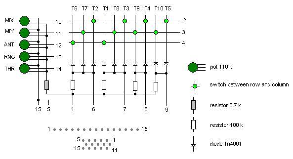
I’ve started with a basic wiring diagram I found for the cougar (I think TM send it to me when I’ve asked for it, but it’s also available online).
with quick deduction, I’ll state the obvious.
The buttons are arranged in a matrix (It took me a while to figure out the inner workings of that – but we’ll get to that).
pin 1 should be 5V (because of the way the diodes are arranged). so it’s used both for the Pots and as a pull up for the matrix (for now we’ll call it “probably”).
pins 5 and 15 are ground, used for the pots.
pins 10-14 are the throttle pots (microstick, ANT, Range and throttle itself).
Now for the matrix itself.
for me it was tricky because I’ve never worked with key matrix and all the examples I’ve found were a bit dodgy.
so I had to play round with the pins (having them marked like this helps).
All examples and tutorial state that Matrix have rows and columns, and there are various libraries for arduino that do some voodoo under the hood to have it detect which specific key was pressed. we need more then that, we need all the keys.
So I’ve played around with it, trying to figure out how it should actually work. it took me about an hour of fiddling with my Uno, but once I figured it out, it’s simpler then I thought.
to explain I’ll change the names usually used. so we no longer talking about “rows” and “colums” but rather “active pins” and “sensing pins”.
the active pins (in this case 2,3 & 4) are all set to high. in this state, because of the pull-up from pin 1. all the sensing pins are also high when read.
Now we initiate a probing cycle.
we pull pin 2 down, because the switches are open, nothing happens. but if one of the buttons on the 2 line (T2, T3, T4 or T5) is pressed. it will pull the corresponding sensing pin down to ground. giving us which button is pressed on pin 2.
We then bring pin 2 back high, and pull pin 3 down, sensing pins are now “connected” to T7, T8, T9 & T10.
Today, while in the shower it hit me why line 4 has only 2 buttons, and why it’s 1 and 6. these are the two push buttons. having them seperated makes it much easier to de-bounce them.
you pull 4 low, sense and store the data, pull the other two. and finish up with pulling 4 again. comparing the first and last values. and de-bounce completed.
I’ll have to figure all that in the code, when I get there. but that’s the idea for now.
The Hardware
So I sat down to design the PCB for this.
I’ve decided to use the Arduino Pro-Micro (32u4) because it’s cheap, and I’ve already figured out how to make it appear as a joystick. – 6USD
because the promicro has only 4 analog pins (which are 10 bits) the TQS has 5 axis, I needed to get external ADC, I got a MCP3202 12 bit SPI device. that’s 4 USD more.
and I needed a breakout board for the VGA connector – another 6$ USD incl shipping
That’s 16USD – and we need some more stuff, which I had laying around. Protoboard, socket, female headers, 10k resistor, and LED and 220 resistor, and a PB for the reset. and only these last items are lost when I decide to drop it. because the expensive parts can be taken off (because of the use of headers).
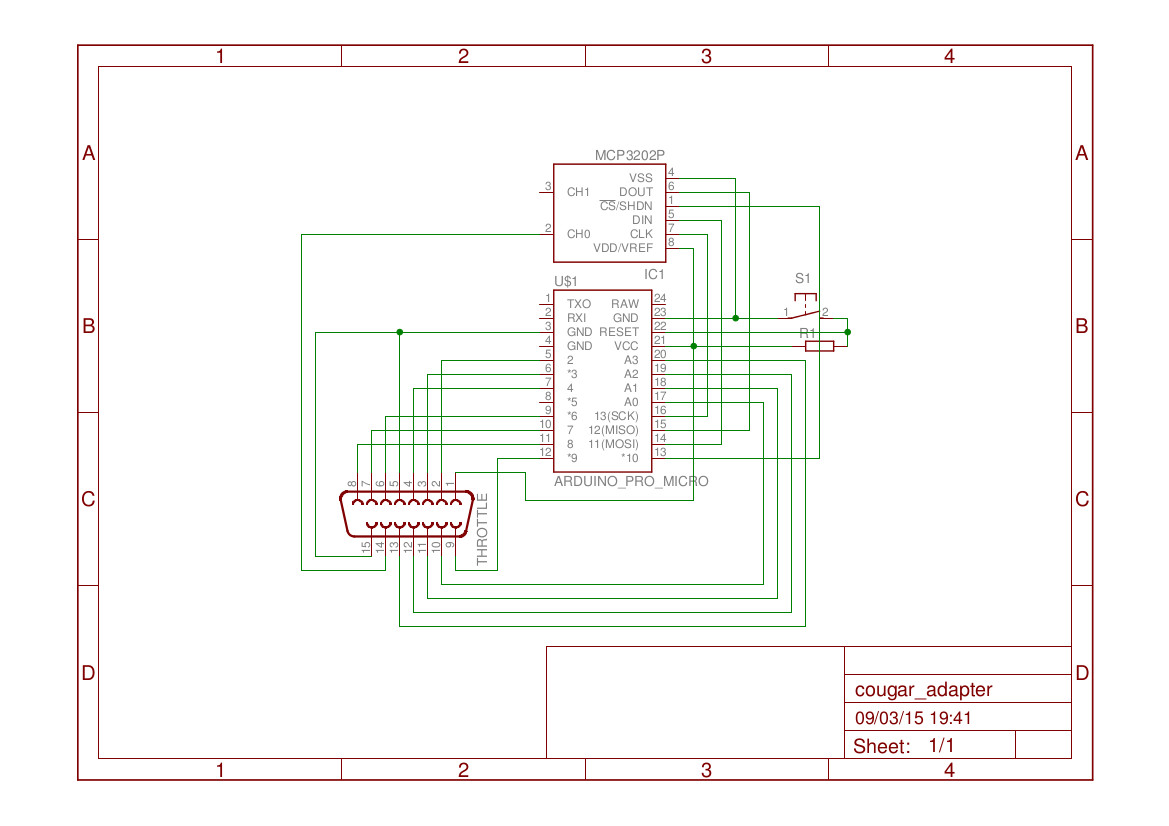
I’ve added an LED connected between power and ground. Just to light up when power is applied. it’s not listed here.
PCB is standard 7*5 cm PCB (I used double sided, but one side would have worked just as well)
Wiring everything up was an annoying task (but it’s still easier then what I’ll need to do for the ICP :\
once wired, it was time to populate the PCB.
I’ve mounted the VGA connector “upside down” in order to lower the total height of everything.
the I’ve connected to the throttle and tested things with a simple Arduino sketch (that just printed axis values, and the sense lines outputs).
That’s all for now 🙂
Software will be looked at in the next posts.