I’ve decided to upgrade my pit and get a Force sensitive mod for my stick. I’m currently using a stock Warthog, and I love it. the grip is fantastic. However, there is only one mod for it, which is the very expensive FSSB-R3 made by RealSimulators. The product seems to be a very good piece of engineering, and is a drop in replacement for the WH, slap the grip on the base and you are done. However, mounting in in a proper stick base is somewhat more problematic. The other Force-sensing mod is the FCC3 by ViperCore.nl it is somewhat cheaper, community proven for years. However, it has a major drawback, it requires the Cougar PCB to work. I have a cougar, but I refuse to use it 🙂 (see my TQS controller series).
But a lack of controller never stopped me 🙂 So I opted for the FCC3 and started to dig into my Cougar to understand what will be required.
In this post I’ll dive into the grip wiring and bit ordering, and all the other fun things I had to dig into a whole bunch of documents to find.
I didn’t write any proper “tech post” in a while. However while working on the ICP I’ve had to re-learn (like everytime) the basics.
This time it’s encoders that got my attention.
The Web is filled with howtos and tutorials about encoders, pages upon pages upon videos. all demonstrating and explaining how everything works.
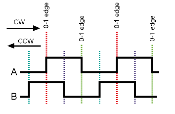
in a sentence or two (or more), Rotary encoders have two output pins, connected to a common pin. When the encoder is in a detent (or stop), both pins are the same state, which is OPEN. when rotated, the pins pulse on and off between the stops, they do it in a staggered way. allowing us to determine rotation direction (and speed) of the rotation. I’ve yet to learn the speed bit, so let’s concentrate about direction. the pulses look something like this:
Rotary Encoder pulses (from the Arduino website)
In this diagram the outputs are pulled down, and the common is connected to 5V. it can of course be the other way around.
to get the state we can use poll, an interrupt pin attached to one of the outputs, or two interup pins. attached to both outputs. the more interrupts you use, the less chance you will miss a pulse causing a step to be missed).
Regardless of the option you choose to use, all the articles have an elaborated list of if statements, designed to figure out which thing goes where.. something in the spirit of:
if (pinA == HIGH) {
  if (pinB == LOW) {
    // it turned CW
  } else {
    //it turned CCW
  }
} else {
  if (pinB == HIGH) {
    // it turned CW
  } else {
    //it turned CCW
  }
}
Anyway, this is long, complex and pretty hard to understand.
But if we create a truth table based on the diagram above it reveals a little loophole.
what triggered/pin status
A1B1
A0B0
A1B0
A0B1
ΔA
CW
CW
CCW
CCW
ΔB
CCW
CCW
CCW
CW
as you can see, the pin that changed, determins the rotation. if we use interrupt on pin A then:
if (pinA == pinB) {
    //it turned CCW
} else {
    // this is CW
}
Interrupt on the B pin will be the other way around.
And if you are triggering on both it’s also quite easy. you just need to use the correct if statement everytime.
I’ve been doing some work on the code, mostly involving i2c commands and addresses. Those are usually given in Hex in the datasheet, sometimes with binary reference, but you might find yourself needing to convert between the two and sometimes to Decimal.
There is a quick way to convert back and forth between all of them by hand with nothing but a piece of paper (you can do it in your head if you are good with numbers – I’m very bad at it :))
In the last two posts we worked with the hardware and basic code for debugging. In this post we will go over the basic changes done in the actual code.
Everything is already available in the download page.
You can browse the code and download all the stuff you need (including a pre-compiled Hex, ready to be uploaded to your device – incl. a simple script to help with it for those of you who only want it to work :))
Here is a small clip showing how it looks in windows.
Now let’s dig into some technical stuff (only if you want to) 🙂
I’ll start with an apology – I’ve been working on prototyping for this for over a week, And I’ve never too a video or a photo of the prototype working on the breadboard. So this post would be somewhat less illustrated then I would have wanted. sorry 🙁
I’ve decided to take the Indexer design concept and use the Shift register chip’s ability to be chained as a way to drive the Cation panel.
F-16 caution panel is made up of 4 rows of 8 lamps – classic for 8bit shift register, I just need to chain 4 of them and presto – the entire caution panel on 3 pins using SPI (CS, SCK and MOSI – where SCK and MOSI are shared among all the other devices anyway).
We’ll start by looking at the Caution panel structure itself.
Well After working on the thing for two months, I’ve got a pretty good concept on what I want to achieve.
I started with DED and grew from there.
The first obvious “victim” was the FFI, as it’s “right there”.
followed by the Indexers (again, “they are just there”).
then I just got greedy 🙂
PFL was next to be added – because “it’s basically just another DED”, closly followed by the caution panel “it’s right next to the PFL, and the code is just a bumped up Indexer”
and then I completely lost it..
and glareshield lights and TWP lights were also included on the roadmap and also the CMDS display – because I can.
But I’m pretty sure the Arduino cannot handle all of this – at least the base would be set for floks that would prefer having TWP over caution panel or CMDS over DED/PFL.
but connecting everything is not as trivial, especially in the cockpit environment – and bread board is out of the question of course.. cables are too fiddly.
So I’ve started thinking about a PCB design to accommodate all this and make it somewhat user friendly to assemble – but still maintain some flexibility.
Let’s talk about a bit about the technical stuff. I think that going over the technical aspects will make some sense, and naturally help others in their quest.
I’ll have posts like that from time to time, covering technical aspects of the project. Which means that code examples, circuit schematics and random technical mambo jumbo are all legit in this type of posts.