I’ll start with an apology – I’ve been working on prototyping for this for over a week, And I’ve never too a video or a photo of the prototype working on the breadboard. So this post would be somewhat less illustrated then I would have wanted. sorry 🙁
I’ve decided to take the Indexer design concept and use the Shift register chip’s ability to be chained as a way to drive the Cation panel.
F-16 caution panel is made up of 4 rows of 8 lamps – classic for 8bit shift register, I just need to chain 4 of them and presto – the entire caution panel on 3 pins using SPI (CS, SCK and MOSI – where SCK and MOSI are shared among all the other devices anyway).
We’ll start by looking at the Caution panel structure itself.
Again, Martin “Pegasus” comes to the rescue with his excellent site: caution panel – xflight.de
As you can see, pre and post block 40 have different caution panel structures, light bits are the same (we’ll get to that) but the order is different. My project is basicly Block 30 jet, however in ITO, the caution panel in the “Barak” is Block 50. however, as the difference is only in bit order – I can support both types pretty easily in software.
The problem is Hardware – producing the labels and structure is not trivial, so I looked around. there are two main options I’ve seen.
the “Classic” option would be ViperPanel’s Caution panel. they produce wonderful items, but at a cost. their Caution panel is around 155USD before shipping
The other option is “Hispapanels” a spanish company that produces pretty much every panel for the F-16 (plus they have an extensive line of Boeing Aircraft panels for Civies). their Caution panel has a significantly lower price (38 Euros Which are around 47USD).
But the off side is the construction is not the same, the hispapanels are more simple in materials and design, but that should be good enough for me – And as I’m on a tight budget that is what I’ve ordered..
Now that we got that covered we can move on to the electronics.
As we can see we got 8*4, our 74H595 shift register can give us 8 outputs – so we need 4 of those chips, and have them chained togeather. So the schematics looks something like this:
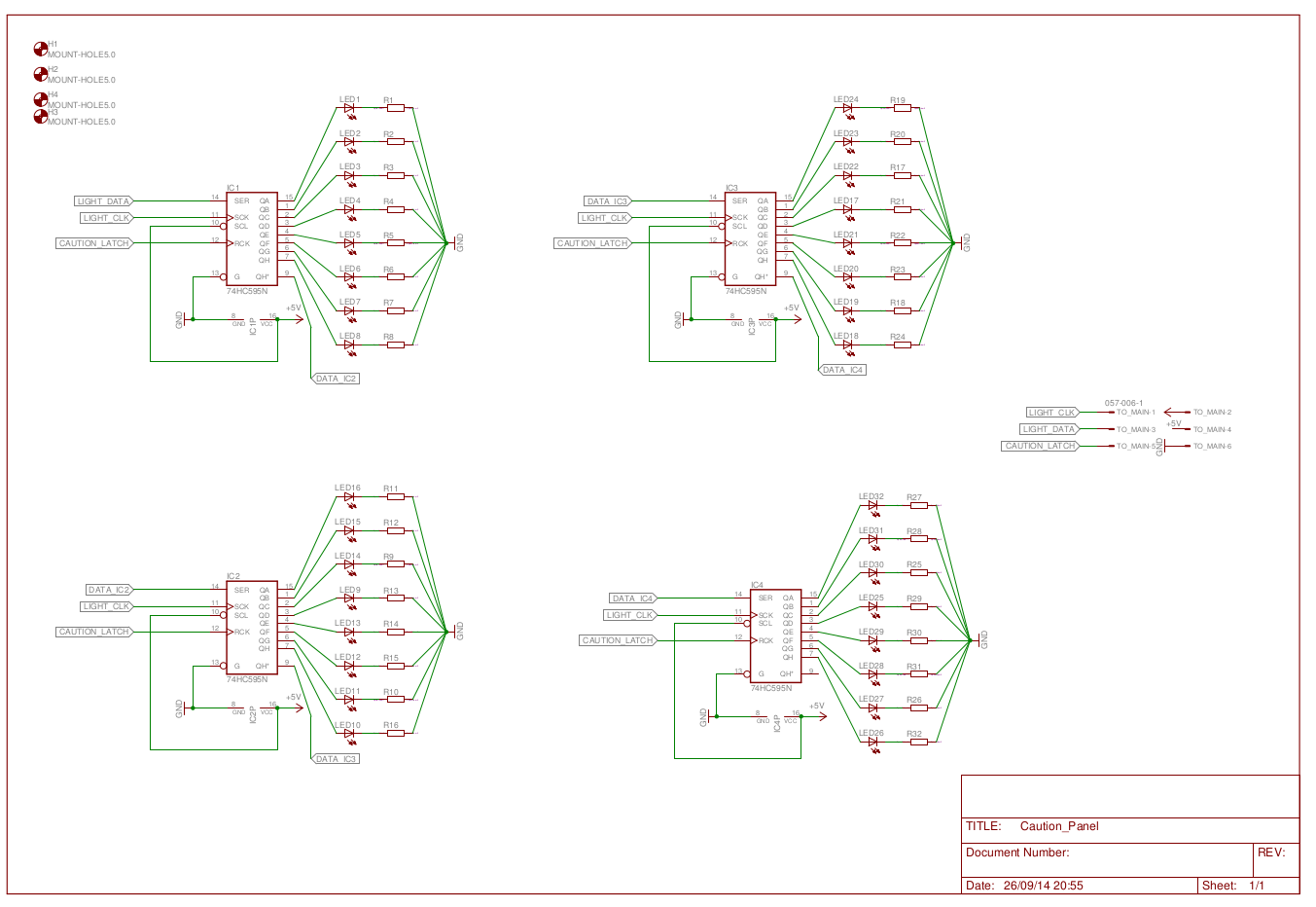
I’ve decided to start by placing the LEDs and resistors,
I’ve got a hellofalot of the 5mm Pirahna LEDs so I decided to use them. they are too tall to fit into the space in the frame, and just barely fit – but I’ve deceded to go with them anyway. the Hispapanel Caution panel comes with a predrilled backplate for 3 mm leds, I’ve decided not to use – I actually kinda destroyed it while trying to drill a 5mm hold for bigger leds, So I’m left with the Pirahanas which I’ll need so space from the caution panel somehow – still not there…
anyways, because of the tight fit, I’ve decided to place and solder the LEDs and resistors first.
Once this was done, I’ve decided to stack the rest and have a separate control board with the shift registers
After wiring the entire thing I realized that connecting the control board to the caution panel will not be trivial so I stopped to think – I have 8×2 female headers I’ve ordered for the screen adapters, which is good, and a 6 pin female header – I’ll use two of them for ground and that fits perfectly on the small prototyping PCB I have. and makes the connection somewhat easier and I’ll be able to replace either (or both) of the boards in the future with ease.
so I sat down on eagle and got something like this:
Once I get to the next batch of PCB orders – I’ll revisit it and make the board nicer . But till then – It’s a guidline to whatever I need to do.
And the wiring begins…
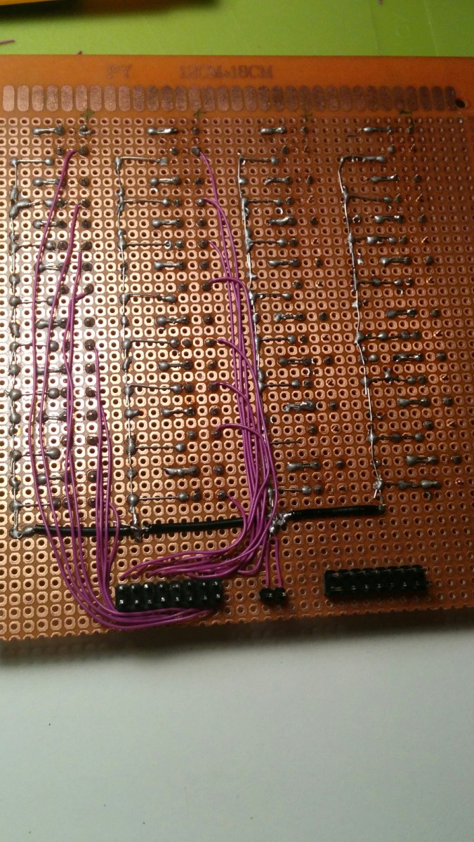
It’s a long and boring task hand soldering the whole thing. but I think this is a good place to finish this post We will continue this after I finish the wiring and test everything. we will then go over the code that drives the whole thing..
BTW, this is probably my last backlog post – and from now we will probably have “real time” updates. YEY!
in addition to that apparently I’ve had a misconfigured something, which in turn caused that no one could register or comment since day one of this blog… I did find it odd not to have spam.. Anyway, now it’s fixed and you can spam away 🙂