I’ve FInally got the PCBs I’ve ordered. it has been a holiday here pretty much all of the second half of September up till mid October. So the post office/customs were barely working – while waiting I’ve noticed a few issues with the main board. which triggered a redesign to Rev.B. In addition, Redneck of Viperpits have pointed out that my PCB design for the Indexers is all wrong, so we have Rev. B on that too.
in the meanwhile – let’s look at Rev.A boards in depth and see what we can find.
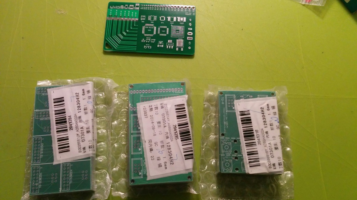
Let’s start from the exciting stuff, this is the first PCBs I have ever made.. yoohooo!
now that we got this out of the system…
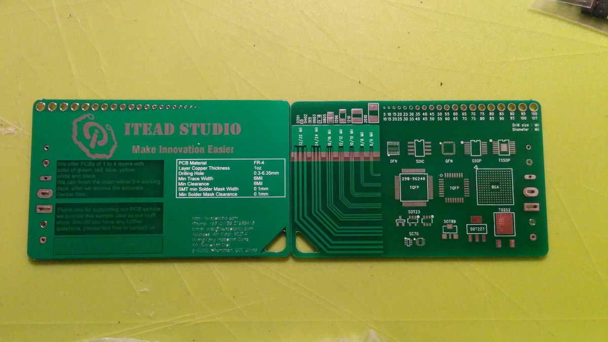
I’ve ordered this first batch of PCBs from ITEADStudio, a Chinese company that offers PCB in a very low price, how low? 10 boards can go as low as 10USD… (depending on board size).
They have supplied a sample PCB with the order showing what they can do:
I’ve ordered 3 10cm*5cm boards and I’ve designed them to cover everything by merging as many needed into one PCB.
- We got a Main board, designed to directly mount Arduino Micro and connect to peripherals. this is a Rev A board, which has a few issues I knew about even before getting it. but I need it for some fitting to make sure the design is solid. modifying it to a working board, is mostly re-labeling of connectors and soldering 3 jumper wires. to fix some design errors – but that will be later on.
- Indexers, Control board and LED PCBs – those boards are “Going to the trash” – because the positioning of the LEDs is wrong. 🙁 but I’ll use them for electrical testing. make sure my circuit works correctly, changing the layout is the easy part.
- screen adapters – I’ve compressed four “DED adapters” and four “FuelFlow” adapters onto a single PCB. if I havn’t made a horrific design flow. they should be OK.
Now that We’ve met the boards, let’s go deeper.
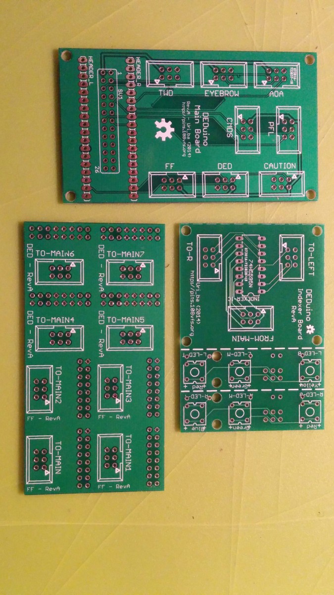
The Main Board
The Main board is the Heart of the project.
I’ve has some wirering issues with it – But those are fixed on the RevB boards which will be in the release. I had to solder in some wiring and change around the lables.
Indexers
The indexers board is actually three boards in one. It’s made up from a driver board, connected to the main board and has the 74HC595 shift register on it – and from there two sub-boards are connected, the actual left and right indexers boards – mounting the LEDs and resistors.
As metioned previusly,
the distance between the LEDs on the boards is a bit off and the project will be released with a corrected board.
Screen Adapters
To simplefy the Display connections, I’ve designed the screen adapters. they are designed for the “BuyDisplay”/”EastRising” 2.8″ and 3.2″ OLED with PCB taking a 2×8 pin header connector. and the Adafruit 1.3″ OLED using 8 pin header. so to simplfy, both boards use the same 2×8 female header and the same 2×3 pin IDC socked to connect to the main board. So once soldered, you just plug in the screen and it works…
While preping the boards, I’ve learned a thing or two about the design and cutting process – so all the boards were redesigned again with a non-unified ground plane, as cutting through the copper layer, damages it and probably causes a lot of heat to escape while soldering components.
I’ve also started to think about a new concept to allow other Arduino boards to connect without any jumper cables – forcing a Rev.C on the main board.
I’ve been thinking about what to include in the first release as it comes near. In my mind I should publish Rev.B of both boards assuming Rev.A is correct electrically – because it’s mostly moving things around and adding labels.
As for the Rev.C for the main board, I would feel a lot better to release it only after I get it and test it as it uses things I’ve never done before – as it’s basically an Arduino shield with a top layer headers for an Arduino Micro. Because it’s supposed to support an Arduino Uno not everything can be used at once – so once jumper wire will be required to activate the future CMDS display if using the shield mode.
anyway, I’ve go the DED ready to go
Then had the entire thing connected
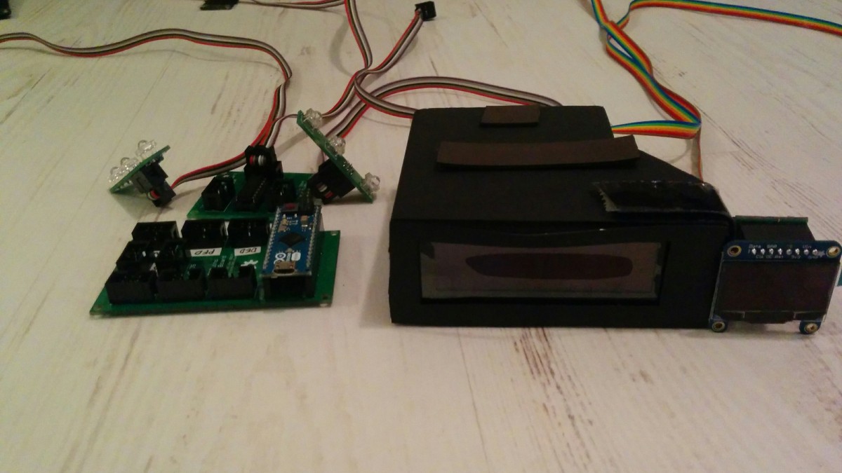
The naturally I’ve mounted everything in the cockpit for testing (including the caution panel not shown here)
Now, I finally could test the whole array at once. and I’ve found some major issues, I’ve been trying to deal with.
with the Due – the light Latch does not work, it seems that the SPI bus is blinking away on all of them – it’s probably to the lower logic voltage – I’m trying to address it – but it doesn’t work for now.
with the micro – I can only use one set of shift registers, either the Catuion panel or the AOA, when both are connected, none works. if I plug one of them out – the other start working normaly.. if no display is connected, they both work. It’s an electrical thing, probably related to voltage on the SPI bus.
I’ve been trying to work around those issues in the passed week – But I won’t delay the release anymore. As this is open source – I hope someone who know better then me about those things will help me find and fix those issues.
3 replies on “PCB – First batch review and notes”
Hello,
I found your website few days ago.
You’ve done a fantastic job…
As you guess, I build my F-16 sim BMS 4.32.
. I bought my Due and a Micro.
. I’m ok with the Buydisplay DED Orange Oled and waiting my Adafruit Fuel Display.
I’ve ordered my female / female connector and the 30 pins flat ribbon.
As I read you, could you indicate to me or brought to me the connectors PCB to Arduino ?
Thanks a lot for your help..
Sincerly
J-Yves
Hi J,
you can find all the schematics needed for the PCB in the download.
if you want to build them yourself, use that as referance.
you can also print them if you like..
however, I might have some boards available for sale, Main board and screen adapters for sure. But I’ll need to make sure.
Uri
Hello Uri
Thanks for reply. As I begin the “Electronic” part of the project, I will be very interested by buying your specific cards “ready to use” so, this way, I’m sure that I’ll won’t add more problem.. 🙂
Could you check and quote ?
Thanks
J-Yves